
----SOLVED----
Thank you to everybody for your assistance. I managed to get to where I wanted thanks to instructions provided by @dual_sport_dork
Thank you, thank you, thank you!
Not sure if anyone can help me here. I am pretty lost and confused and wouldn’t mind if someone could ELI5 something for me.
I’ve never used a real CAD software before yesterday night and I’m struggling a bit, I tried googling things but it’s just sending me deeper into a rabbit hole of things I do not understand yet.
I’m trying to make this speaker enclosure I’ve seen just to do something with this shitty bluetooth speaker I have, so I decided to recreate the enclosure myself.
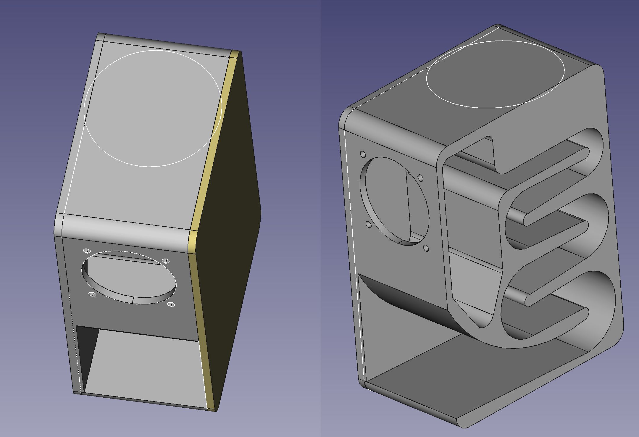
Long story short, I realized I kinda screwed myself after disassembling the bluetooth speaker and now I need to make a 2mm deep pocket on top of the case to snap in the buttons module. I don’t really feel like starting the design again from scratch.
Anyway, as you can see in the attached image, I need to make a big round pocket on top, but both side panels are separate bodies so my pocket only goes through the main body and ignores the 2 other bodies.
I can think of other ways to achieve what I want but I’d really like to figure out a way to do it from where I am right now, if possible. I’ve seen the term shape binder and “union” in my searches but I can’t quite figure it out.
Thank you to anyone who bothered reading this lol
EDIT: For anyone who might see this and is curious about how the enclosure is performing, I finished printing the main body and assembled it to test. Am still missing the side panels and I have to design some kind of flange cover for the driver but here’s what I got so far:
Shape binder is what you need. Shape binder can be used to reference geometry from another body. What I would do is I’d make one pocket on the main body. Then select another body and make it an active body. Then select the pocket you made (the surface or the edge) and create a shape binder (part design). This will effectively import the selected feature from the first body and you can reference it from second body. Make sure you hide the first body, as it somehow gets in the way of shape binder, for some reason. Repeat for third body.
Oh, I actually got it working now using @dual_sport_dork’s instructions but I will save your comment because that is probably the better way to do things. I’m sure I’ll encounter the need for it soon enough hahah. Thank you!
There is indeed multiple ways of doing anything in freecad. But over time, I prefer staying in Part design as much as possible as this makes it more modifiable and customizable and there are plenty of reasons more for me. But in the end - whatever works is good enough.
Yeah I will keep that in mind for future parts I make. For now though since this is my first time using CAD software I’ll stick with good enough hahah